Building an IT Home-Lab Network | Part 1: ISP configuration parameters
Table of Contents
Previously: Building an IT Home-Lab Network | Introduction.
Replacing the ISP Router and Planning the Network
Since the goal is to replace the ISP-provided equipment, the first step is to check what configurations are required for the services they deliver. That way, we can replicate them on our own gear.
In our case, we want to keep three things working: internet, VoIP and IPTV.
Gathering information
Step one: let’s peek into the little router’s web interface.
I’m including a sample screenshot here of how it looks but there is currently no configuration saved!
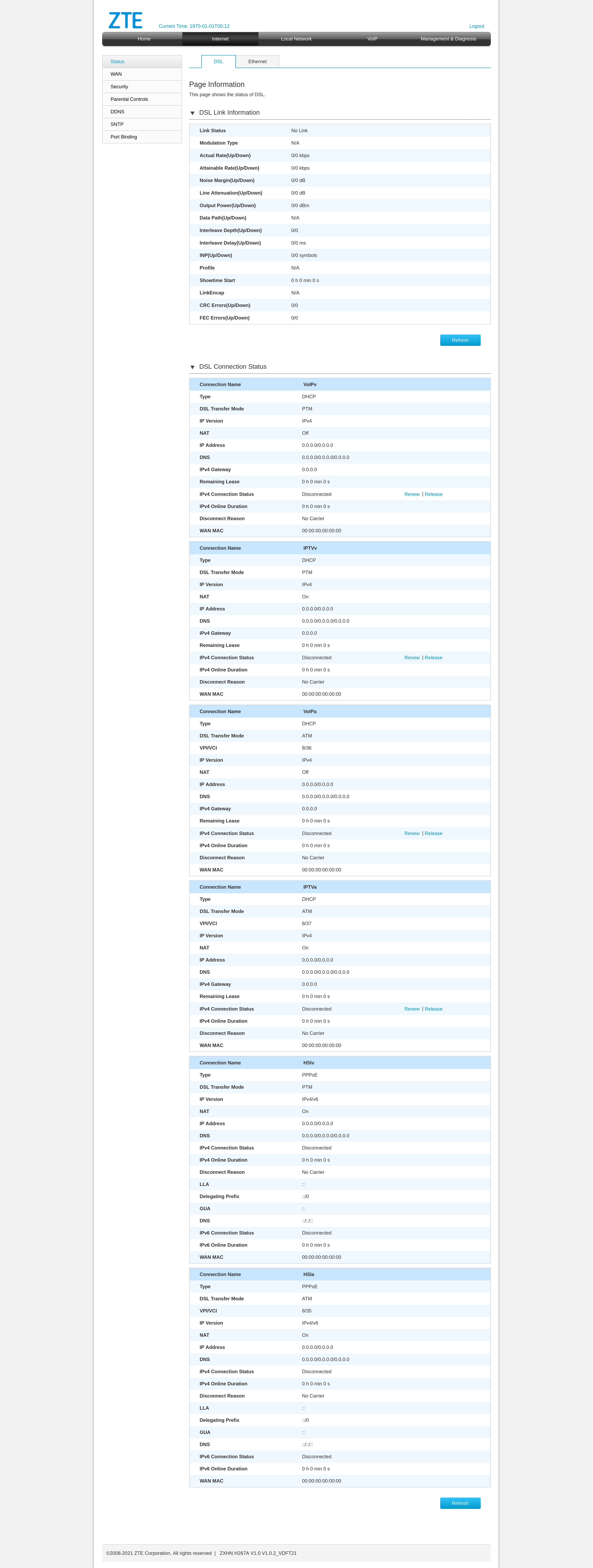
From the interface we can pull some DSL link information, which could come in handy later when setting up the DSL link on our own modem (the C887VA). We also see that the internet service runs over PPPoE and we can gather some basic details about IPTV and VoIP.
The catch? This device is a bit locked down. Some information just isn’t visible and more importantly, we can’t see the password used for PPPoE authentication.
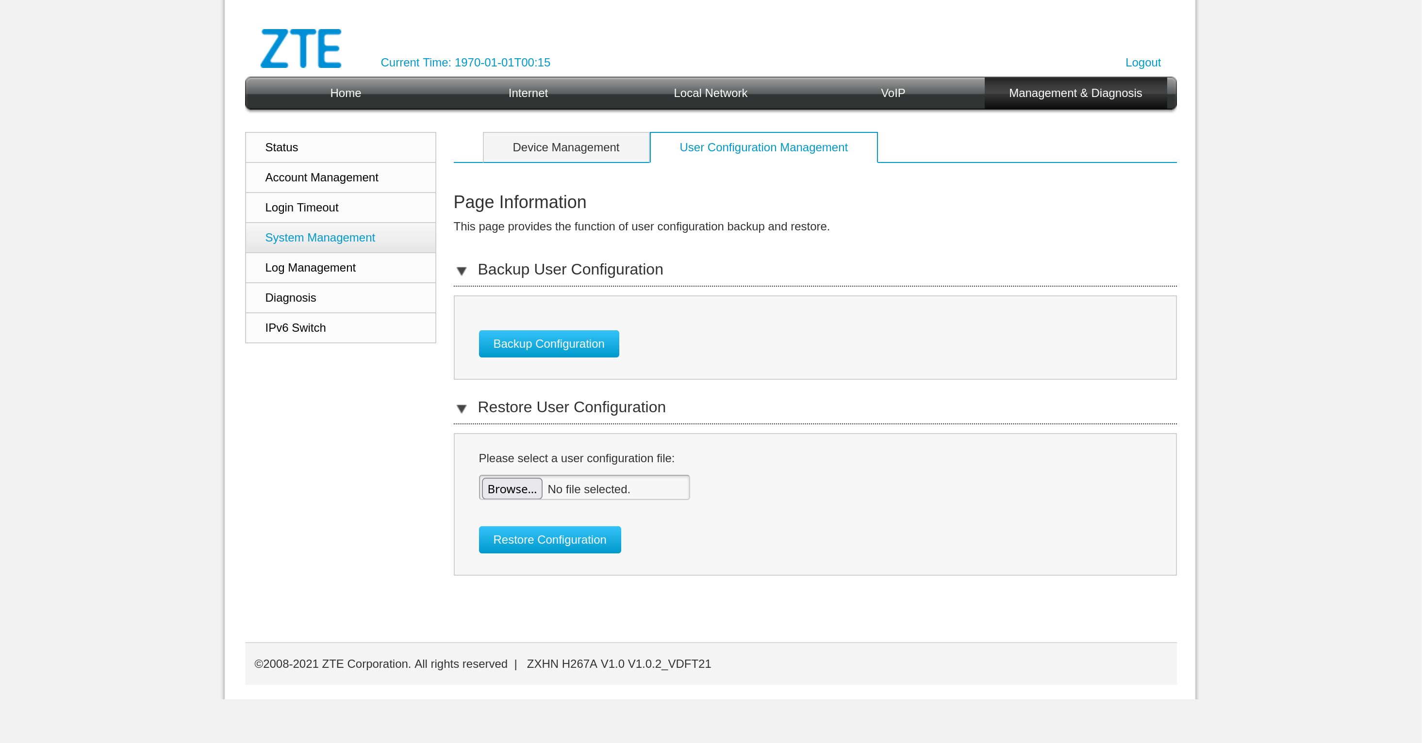
Dumping and decoding the config
So, plan B: let’s dump the config file and take a closer look.
The configuration turns out to be encoded:
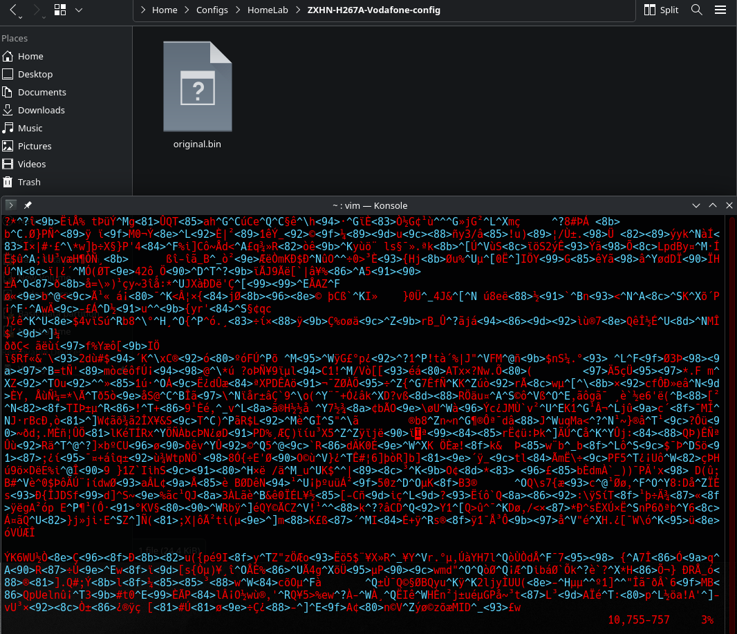
but with a bit of searching I found this handy decoder:
–> mkst/zte-config-utility by Mark Street.
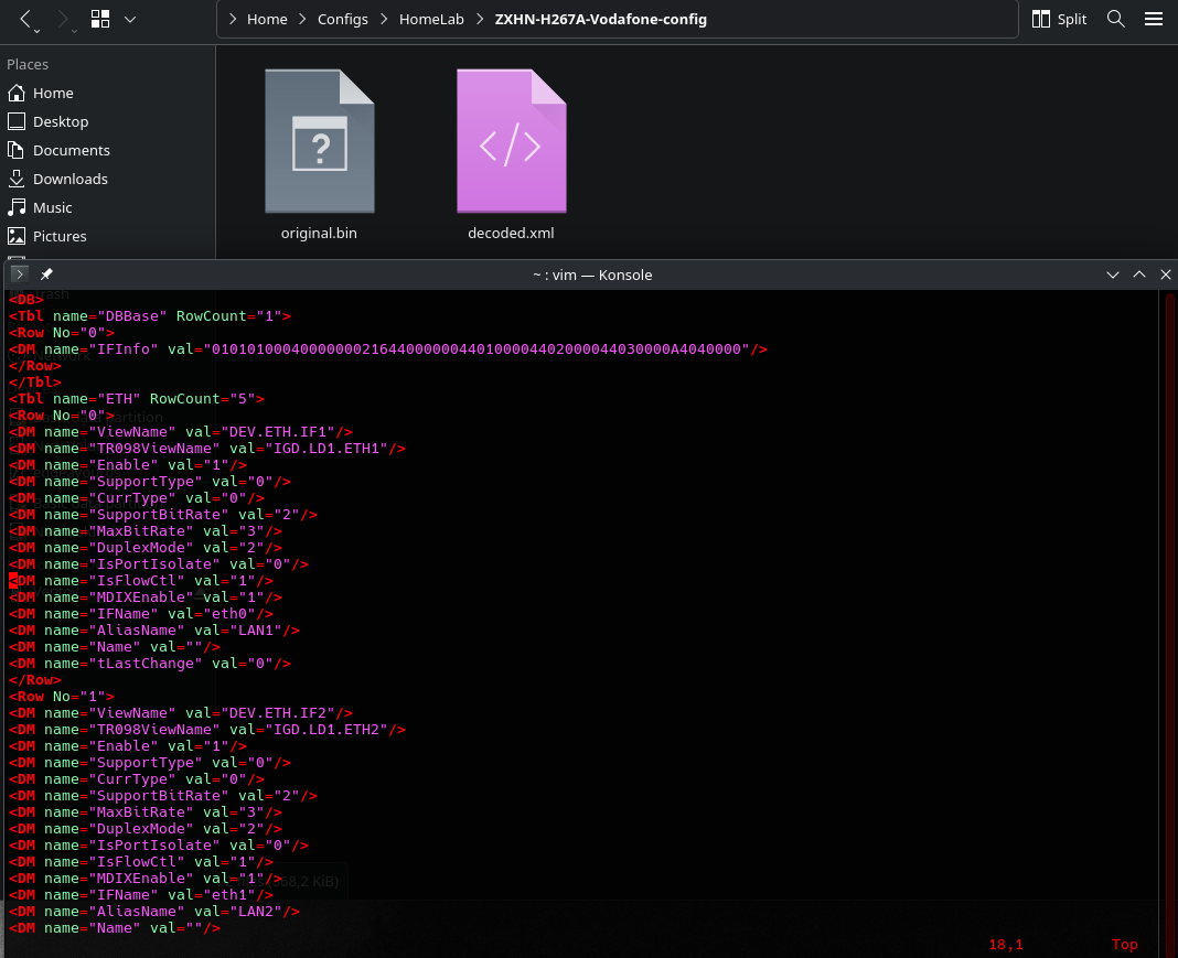
It works right away for this model and once decoded, we can skim through to find what we need: PPPoE username, password, SIP trunk authentication details, etc. The file isn’t exactly bedtime reading, but the key info is there.
Hidden root
And then… surprise! We stumble on a section that reveals root user info.
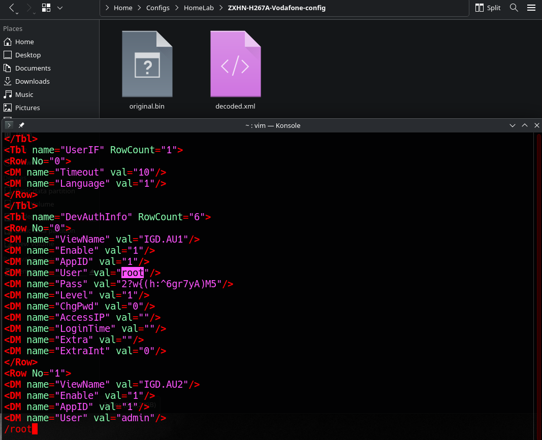
Yep, basically a backdoor account to the device. Logging in with these credentials unlocks the full interface with every setting laid bare.
Much easier to read and suddenly everything becomes customizable. How convenient!
Not necessary after all…
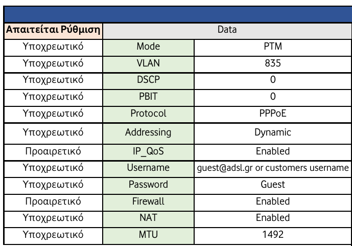
After some further digging, I realized that the ISP (thanks to recent regulations) actually provides customers with full configuration details to support using their own equipment.
Example from the “Data” section:
Oh well at least I had some fun while hunting these down on my own!
So really, there are multiple ways to get what we need. Depending on the ISP, it might take some persistence, but hey, where there’s a will there’s a way ;).
What we have learned so far
I will give you the summary while skipping gritty details like MTU settings…
The most important info I gained from all this digging around is:
- The internet service flows in VLAN 835 and is provided via PPPoE, we now have the credentials required for authentication.
- The IPTV service travels in VLAN 836, a private network exists there, we can join via DHCP.
There the service is provided via multicast streams, so we will have to join these and see how to properly forward them to any IPTV client. - VoIP is provided within a private network in VLAN 837, we should also be able to join the network via DHCP.
We have authentication information required for registering a SIP trunk.
So now if you look back at our diagram of the whole topology.
It’s more clear why I have setup sub-interfaces ETH 0.835, ETH 0.836 and ETH 0.837.
These are the initial point the traffic enters in our “modem” for these services.
Downstream on pfSense are the actual interfaces that live in these networks.
igb0.835: get’s our public IP address to reach the internet,igb0.836: can get an IP address in the providers private IPTV network,igb0.837: get’s an IP in the VoIP network.
Planning the network
Now that we’ve got the configs for the services, let’s plan out the network on our side.
We’ll use the 10.0.0.0/8 private range and carve it up into VLANs, with the third octet hinting at the VLAN ID.
Here’s the breakdown:
| Name | Network | VLAN |
|---|---|---|
| Management | 10.0.10.0/24 | VLAN 10 |
| A.P. Management | 10.0.11.0/30 | VLAN 11 |
| Guest | 10.0.20.0/24 | VLAN 20 |
| IPTV | 10.0.21.0/30 | VLAN 21 |
| LAN | 10.0.30.0/24 | VLAN 30 |
| Lab | 10.0.31.0/24 | VLAN 31 |
Looking back again at the diagram I shared in the introductory post, things should start making more sense.
You can see how all of these VLANs are defined as igb2 sub-interfaces on pfSense (more details on this in the pfSense post).
Downstream you can see how the switch handles these and on which interfaces they end-up on.
Why this layout?
The logic:
- One network for general management.
- A separate /30 just for the A.P. management interface, since this particular access point insists on sending untagged packets.
To avoid messing with the native VLAN, we carve out a tiny subnet just for it. - A guest network, isolated from the rest.
- A /30 for IPTV, mainly to stop multicast traffic from turning into broadcast storms on Wi-Fi.
Our A.P. doesn’t do multicast snooping, unfortunately. Yet another reason to invest in higher-end A.P.s when possible. - Finally, two networks for personal use: one as the daily driver (LAN), the other as an isolated playground for lab experiments (Lab).
Conclusion
We have what we need to get started!
Also a plan for a solid starting structure. More VLANs and subnets can always be added later as the network grows.
Next part: Building an IT Home-Lab Network | Part 2: Configuring Cisco C887VA as a VDSL modem