Building an IT Home-Lab Network | Part 3: Setting up pfSense on an old Intel platform
Table of Contents
Previously: Building an IT Home-Lab Network | Part 2: Configuring the Cisco C887VA as a VDSL modem
pfSense
One of the great things about pfSense is that it can run on almost anything. It’s perfect for re-purposing older hardware into a serious firewall/router.
The only real requirement: get yourself a decent Intel NIC.
- You’ll ideally want at least two interfaces, for WAN and LAN.
- In this setup we will actually utilize all four interfaces of our card.
- Intel NICs are officially recommended and generally provide a trouble-free experience.
- Luckily, used Intel cards are inexpensive and easy to find.
My Hardware Setup
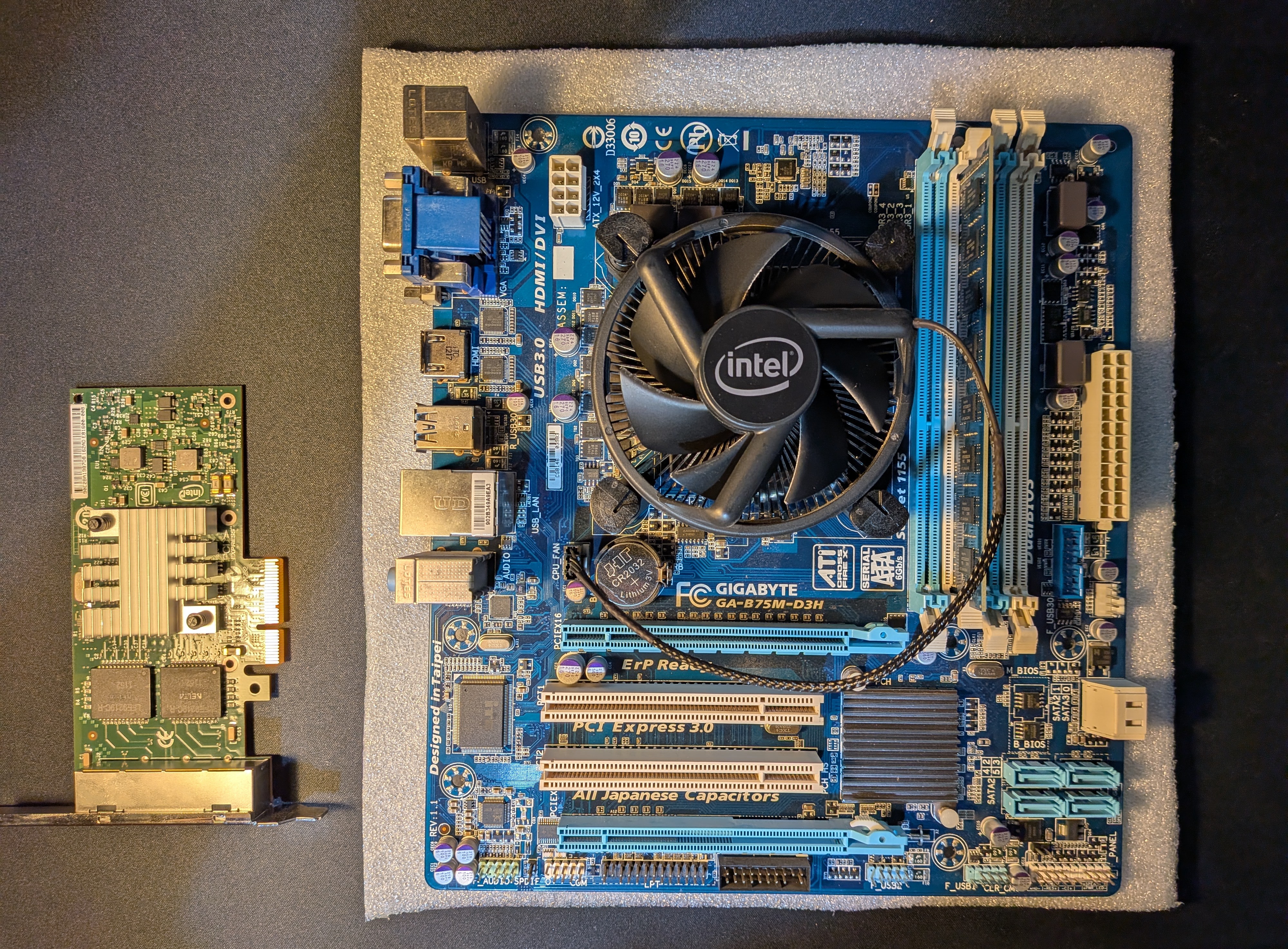
For this build I’m using:
- CPU: Intel i3-3240 (dual-core, 2012)
- RAM: 4 GB DDR3 (single channel)
- Storage: currently running off a USB stick (not recommended!), good timing to do a fresh install on an SSD
- NIC: INTEL 4-port Gigabit (I340 T4)
This CPU works well enough, but it does lack modern crypto extensions that accelerate VPN performance.
Keep that in mind if heavy VPN use is in your plans. Most modern CPUs do include these.
Downloading pfSense Community Edition
Grab the latest installer from Netgate:
–> pfSense Download Page
Yes, the “add-to-cart” procedure is a bit odd, but it’s free.
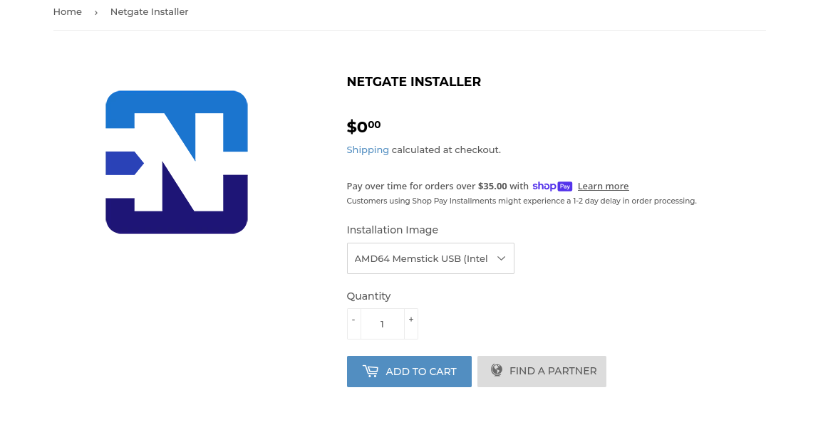
For our case we choose:
- AMD64 Memstick USB (Intel x64 Netgate appliances)
Always check the hashes: –> SHA256
Example check:
echo "hash_value  image_file_name.img.gz" > file_name.sha256
sha256sum -c file_name.sha256
Decompressing the image:
gunzip netgate-installer-amd64.img.gz
Creating a Bootable USB using dd
Classic setup.
- Plug the USB in and
lsblkto identify the device - Make sure it’s not mounted:
sudo umount /dev/sdX - Format to FAT32:
sudo mkfs.vfat /dev/sdX sudo dd if=/path/to/image.img of=/dev/sdX bs=4M status=progress
BIOS / UEFI Settings
Before installation, let’s check for any useful BIOS settings:
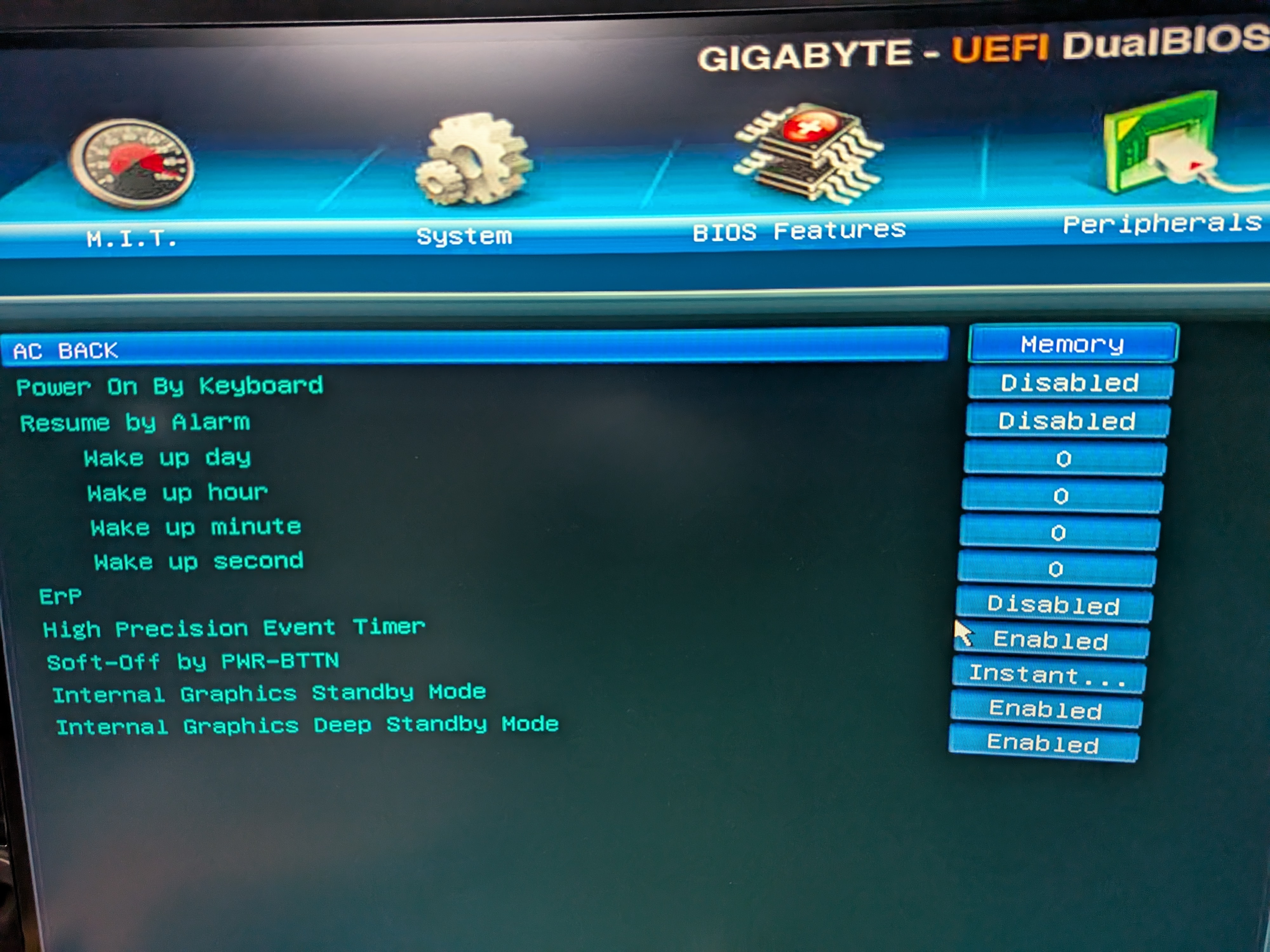
- AC BACK (or similar): enable this so the system powers back on automatically after an outage.
Initial pfSense Setup
- Connect at least two interfaces: WAN + initial LAN.
- I am connecting
igb0to C887VA’sFE0. Alsoigb1to my PC’s NIC but only temporarily. - The goal is the final topology illustrated back at the introduction.
- I am connecting
Now connect the USB stick, HDMI output, a keyboard and boot!

- Configure the WAN interface per your ISP specifications, here I input the proper PPPoE values.
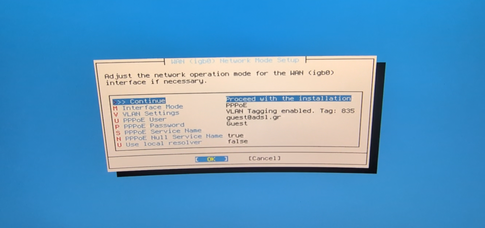
- For LAN, start with an untagged interface for initial setup. We will change that later.
Take note of the interface IP because it will be used for management via the web UI.
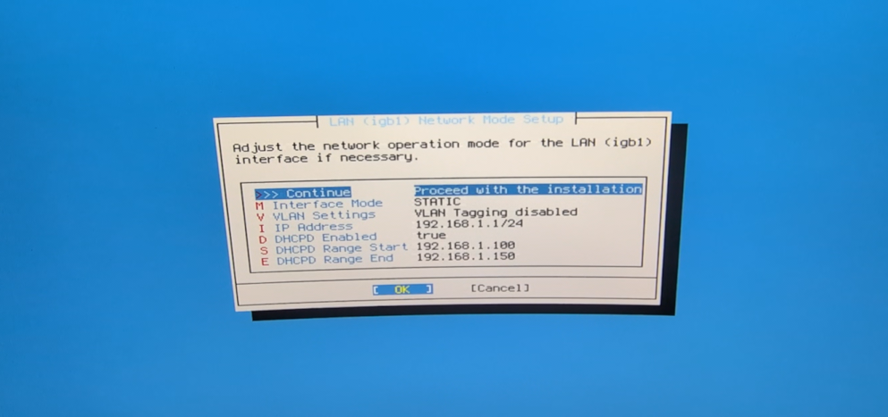
- There are some more steps but overall they are trivial to follow, after the final reboot you should see this screen:
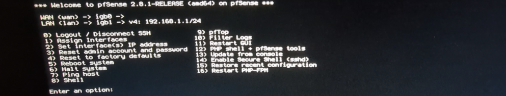
That’s all, now we can use the web-management interface!
Basic Configuration
Getting started
To access the web UI, visit https://ip_of_LAN_interface (192.168.1.1 in this case) in a browser from a PC connected to the LAN interface.
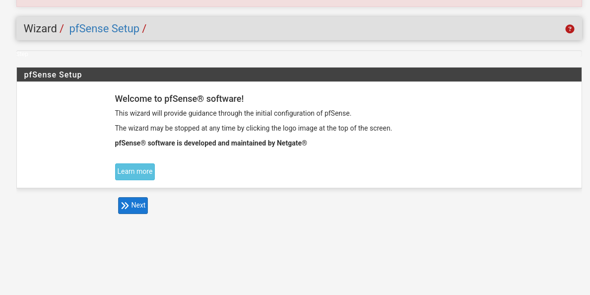
What follows is another very simple configuration wizard, so I won’t flood the page with screenshots, here we will set-up our WAN again and an administrator password.
Note: In this wizard, at the time of writing, I couldn’t set up a VLAN for the WAN interface.
Since our WAN requires VLAN 835 tagging, this initial untagged setup will need to be adjusted immediately after.
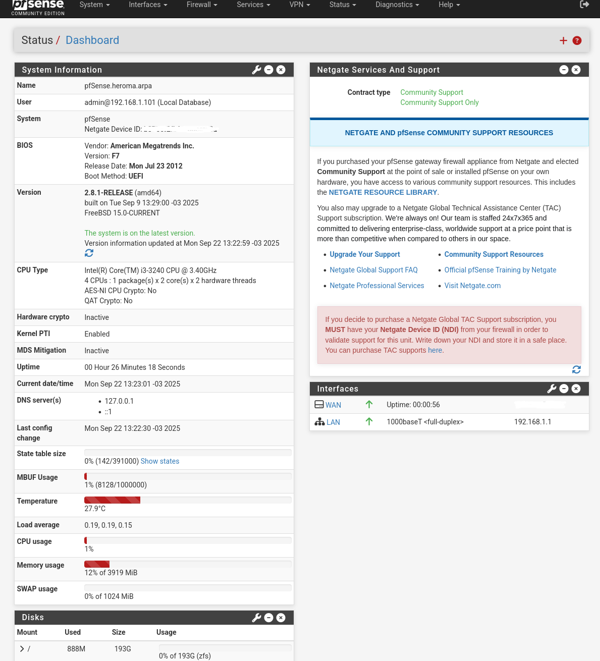
Once we hit the “Dashboard”:
We can go over to the “Interfaces / Interface Assignments” menu and choose VLANs.
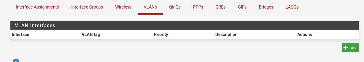
Hit “Add” and this is how we add the 835 VLAN for the PPPoE connection.
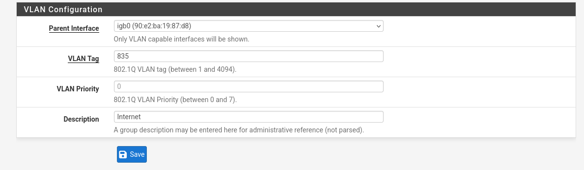
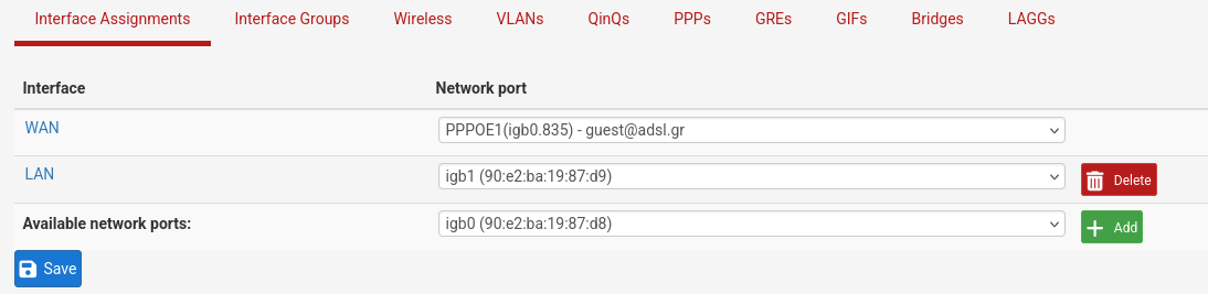
Now go back to “Interface Assignments” and assign igb0.835 to WAN, inside input the correct values for the PPPoE connection once again.
This is what it should look like in the end:
Extra settings
Under System/Advanced there are a few settings to check:
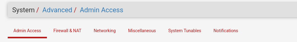
- Admin Access: make sure HTTPS is checked
- Networking: switch to Kea DHCP
- Miscellaneous: Cryptographic Hardware / Thermal Sensors: set according to hardware support
- Notifications: Interesting options here, worth exploring for a future post (Telegram notifications, etc.)
Interfaces:
Now similarly to how we set up the WAN sub-interface let’s set up the rest of our interfaces, again according to the introduction diagram and the network plans.
First let’s configure the VLANs.
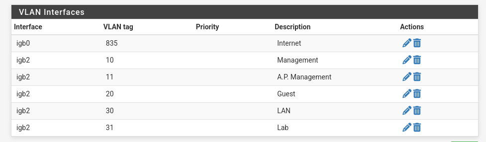
- Don’t worry about IPTV and VoIP for now, we will set these end-to-end after we are done with the basics.
- Make sure to select the proper parent interfaces.
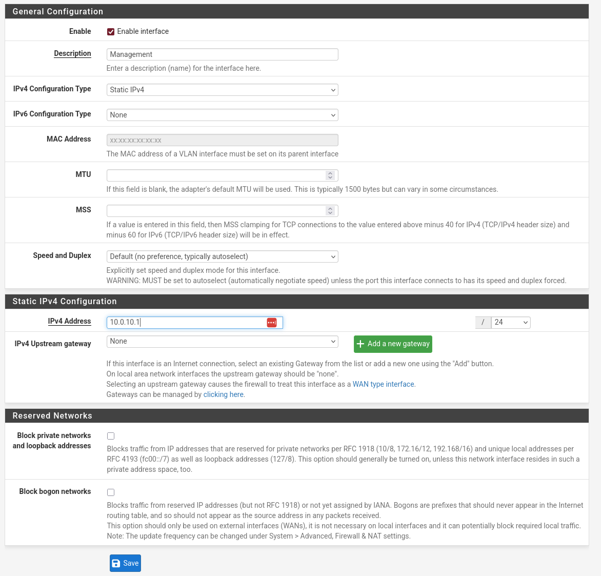
Then we assign accordingly and go into each interface’s settings.
Enable, set it up with a Static IPv4 (the first one available in the network) and make sure to input the proper subnet mask according to the design.
- Leave the VLAN 30 int with the OPT4 name for now, we will rename it (and repurpose the one currently named as LAN) after we are done setting up the VLANs on the switch.
- Reminder: the LAN interface is a temporary untagged interface serving as our initial access to the configuration UI.
Our plan is for “LAN” to be the interface tagged with VLAN 30.
- Reminder: the LAN interface is a temporary untagged interface serving as our initial access to the configuration UI.
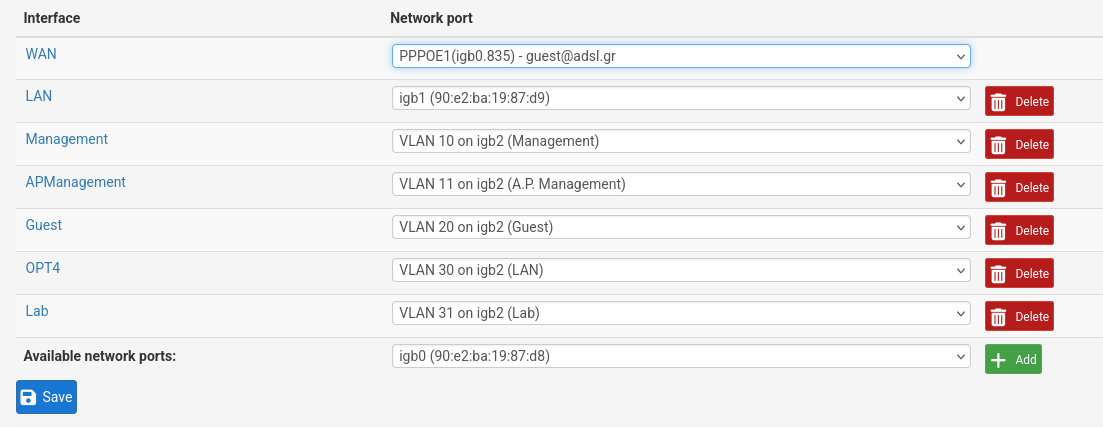
- So the end result for now is:
- Our WAN interface set up with PPPoE credentials. Public IP.
- A default LAN so that we can access management for now. IP: 192.168.1.1/24
- Management on igb2.10 (VLAN 10). IP: 10.0.10.1/24
- APManagement on igb2.11 (VLAN 11). IP: 10.0.11.1/30
- Guest on igb2.20 (VLAN 20). IP: 10.0.20.1/24
- OPT4 (Temporary name, future LAN interface) on igb2.30 (VLAN 30). IP: 10.0.30.1/24
- Lab on igb2.31 (VLAN31). IP: 10.0.31.1/24
Firewall:
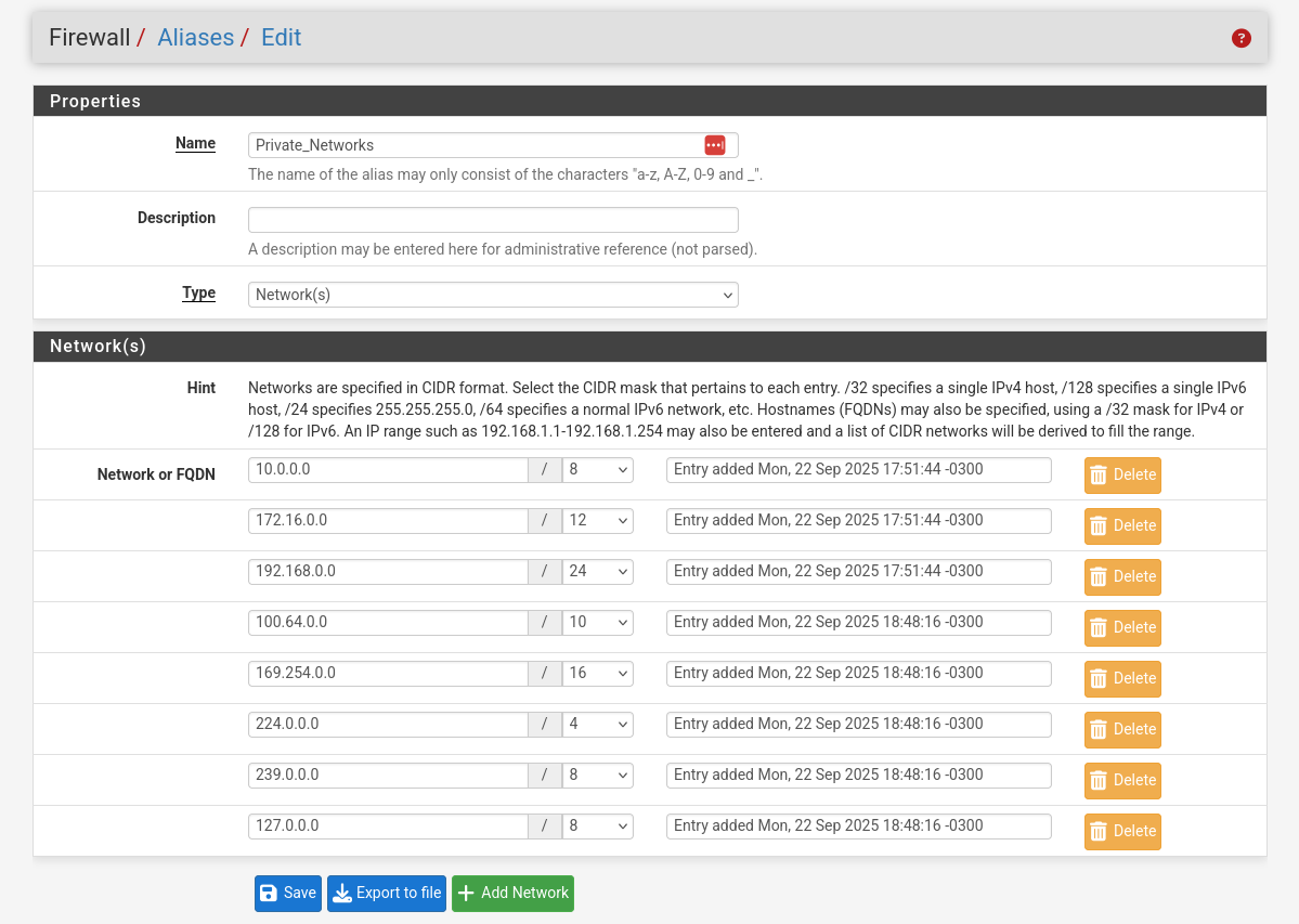
- I’m creating an alias to make setting up the firewall a little easier.
- The goal is to create an alias that covers all of our internal networks, so just RFC1918 networks should be good.
To be more thorough, I included all private address ranges. Just to avoid any future or weird cases.
- The goal is to create an alias that covers all of our internal networks, so just RFC1918 networks should be good.
- Let’s set up our Rules per interface.
First of all I create two rules, one to block access to pfSense and one to everything else, I create these here (not really needed) to start and then copy them to all interfaces.
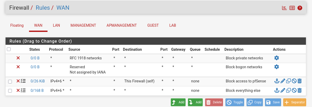
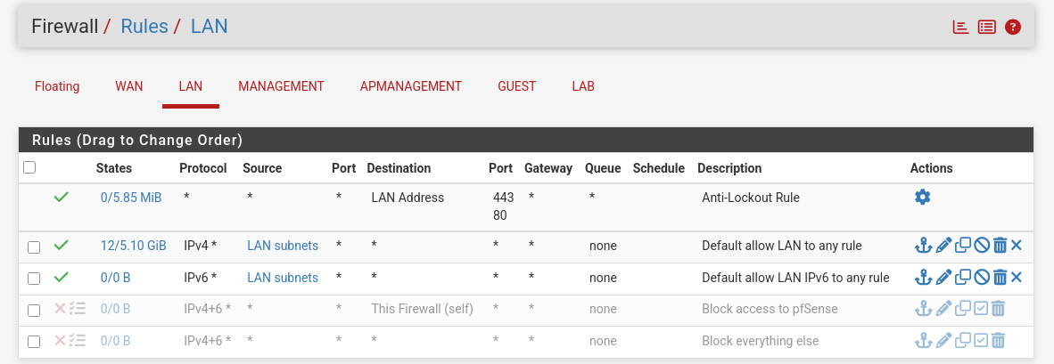
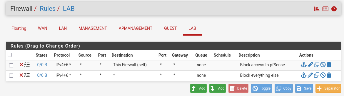
- I keep them disabled for the LAN interface to allow unrestricted access, this interface is a place holder.
Make sure OPT4 has the same rules copied.
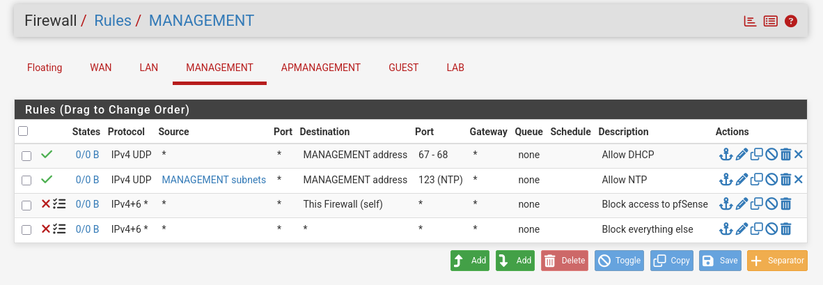
- For Management I want the DHCP service to work properly and NTP.
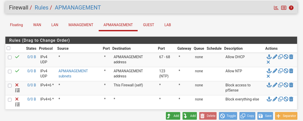
- Same for the AP Management.
- For our Guest network we will also include DNS and utilize our Alias to allow access to the internet without also allowing access to our other networks.

- Finally for now we will keep the Lab network closed off and create rules as needed.
- This is how OPT4 should look like (sorry if it looks a little weird I took this screenshot later due to a misconfig).
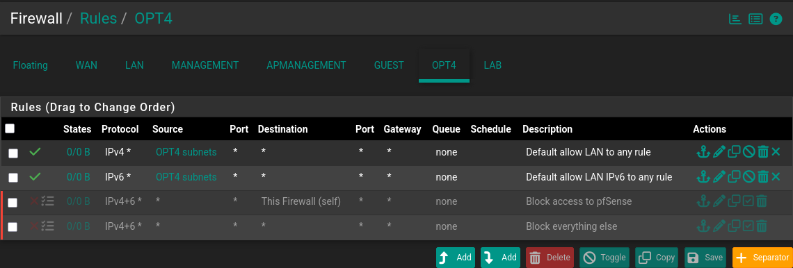
You can see from the little icon (next to the red X) that I have enabled logging for all the Block rules for now. It’s good to log a little more intensely in the start and down the line we can stop logging for stuff that fills up our logs with unneeded noise.
Services:
- DHCP Server
- Under Services: DHCP server we can easily set up our DHCP.
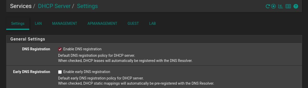
- First of all a cool little setting is: Enable DNS registration, enabling easy resolving of local devices hostnames.
- BTW yes I did change my theme mid-setup.
- For the LAN we can keep it at default for now.
- I don’t enable the service for the LAB interface.
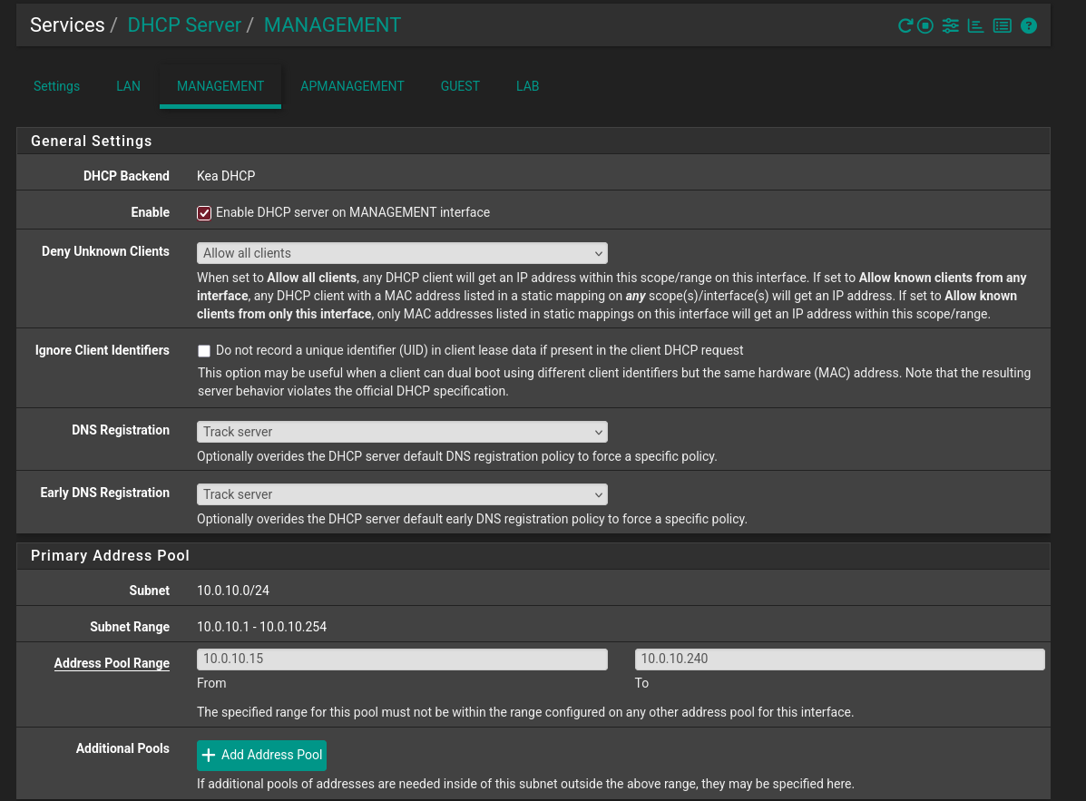
- For MANAGEMENT, APMANAGEMENT and GUEST I keep the same settings but adjusted for each network’s subnet.
(10.0.10.0, 10.0.11.0, 10.0.20.0 accordingly). - The OPT4 interface should also show up here, there was a misconfig when I took this screenshot.
For it we use the 10.0.30.0 network.
Here is the MANAGEMENT interface for example.
As you can see I like to leave a few addresses at the start and end of the subnet.
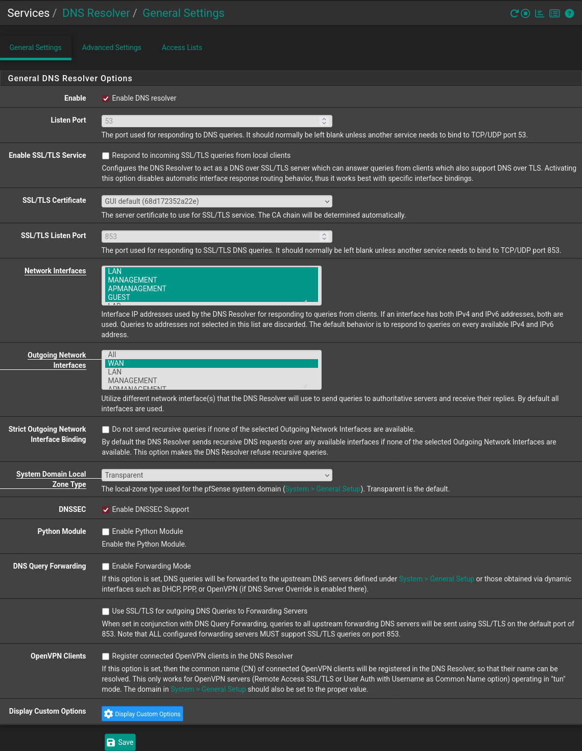
- DNS Resolver
- While it has bugged out on me a few times I do like to utilize the DNS resolver installed by default on pfSense,
it will query root servers directly and keep a local cache.
Here is how I set mine up:
- I like to explicitly set the interfaces (including the localhost which can’t be seen in the picture), but keep in mind that you will need to update these accordingly if you want more interfaces to utilize the service.
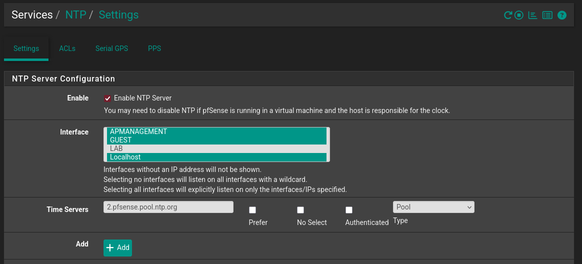
- NTP Server
- Finally I enable the NTP service using just these simple settings and the default NTP pool.
- In a next post we will also utilize the IGMP service built into pfSense for our IPTV setup.
Dashboard and Backup
Once you’ve got the basics working feel free to look around for any other interesting tweaks.
For example customizing the home dashboard should not be missed!
You can basically do a little pfSense rice here ;)
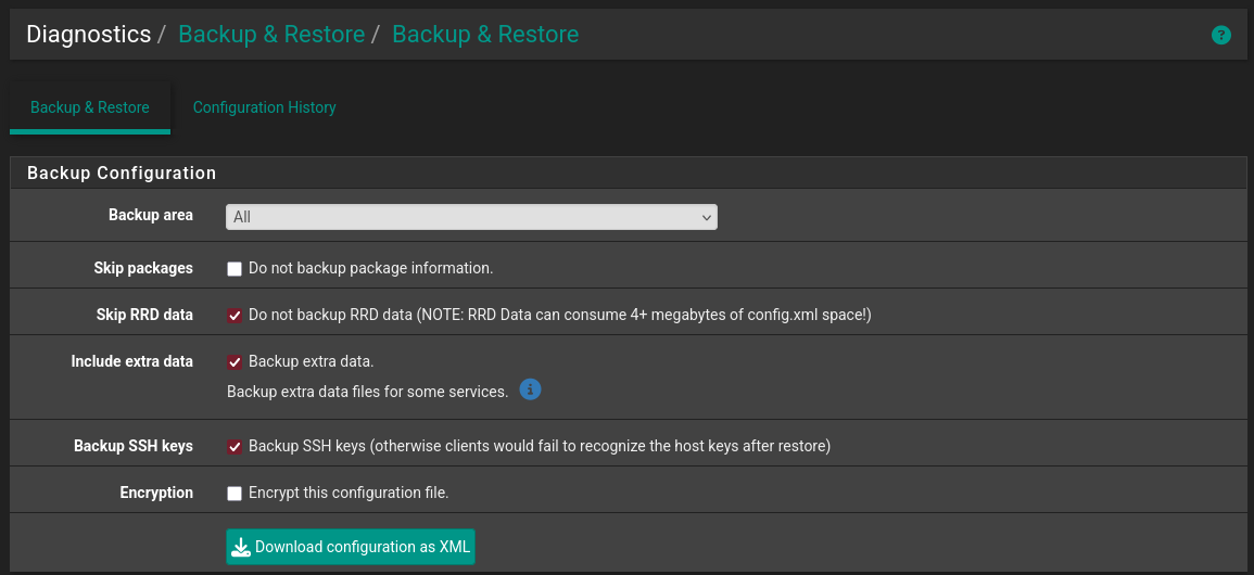
- Don’t forget to backup the configuration!
That’s the core setup. After we set-up our switch with the appropriate VLANs we will come back to remove the native interface.
After the whole infrastructure is ready I will also detail how I configured IPTV and VoIP end-to-end.
Next part:Building an IT Home-Lab Network | Part 4: Cisco SG500 switch configuration