Building an IT Home-Lab Network | Part 4: Cisco SG500 switch configuration
Table of Contents
Previously: Building an IT Home-Lab Network | Part 3: Setting up pfSense on an old Intel platform
SG500

Starting off with this switch we want to update it to the latest possible software like we did with the C887VA.
The good news is that we can actually legitimately download it from Cisco’s website!?.
Oh no… at the time of writing this I realize that Cisco no longer hosts the software/firmware images on their website so I guess I am lucky to have been able to get a copy from them.
Firmware Versions
There are two firmware files you can upgrade here, the Boot firmware and the Active Image firmware.
My switch came with:
| Firmware Type | Version |
|---|---|
| Boot | 1.3.7.01 |
| Active Image | 1.3.7.18 |
The latest versions are:
| Firmware Type | Latest Version |
|---|---|
| Boot | 1.4.0.02 |
| Active Image | 1.4.11.5 |
To reach the latest version, I first had to install the latest boot image, then an interim active image (1.4.1.3) and finally the latest active image.
MD5 Hashes
If it is of any help, here are the MD5 hashes I calculated for these files:
| File Name | MD5 Hash |
|---|---|
sx500_boot-14002.rfb |
accbdaec117726d0e5149babc5b2a0b0 |
sx500_fw-1413.ros |
f73388df555545d4ac56b89a208493c9 |
sx500_fw-14115.ros |
c02a90a3873ec960a0a990ff36080954 |
Accessing the Switch
To access the switch for the first time we reset it via the reset button and it will get its default management IP of 192.168.1.254 and we can use that to gain access to the web UI.
Of course, we’ll also need to connect our PC’s NIC with one of the switch’s ports.
Since there is no DHCP service active, we will manually assign an IPv4 address to our NIC in the same subnet as the switch’s interface. Like we did to set up the C887VA.
I am running Network Manager, so I first disable any currently active connections:
nmcli conn                            #to check the connections
nmcli conn down Wired\ connection\ 1  #disabling active connection
Then check device names and assign an IP:
ip a                                       #checking IP assignments and device names
ip address add 192.168.1.77/24 dev enp6s0  #enp6s0 is the name of my device

Default credentials are cisco / cisco and thankfully we are prompted to change that.
Backing Up and Upgrading via FTP
Backing up and then upgrading the images is fairly straightforward.
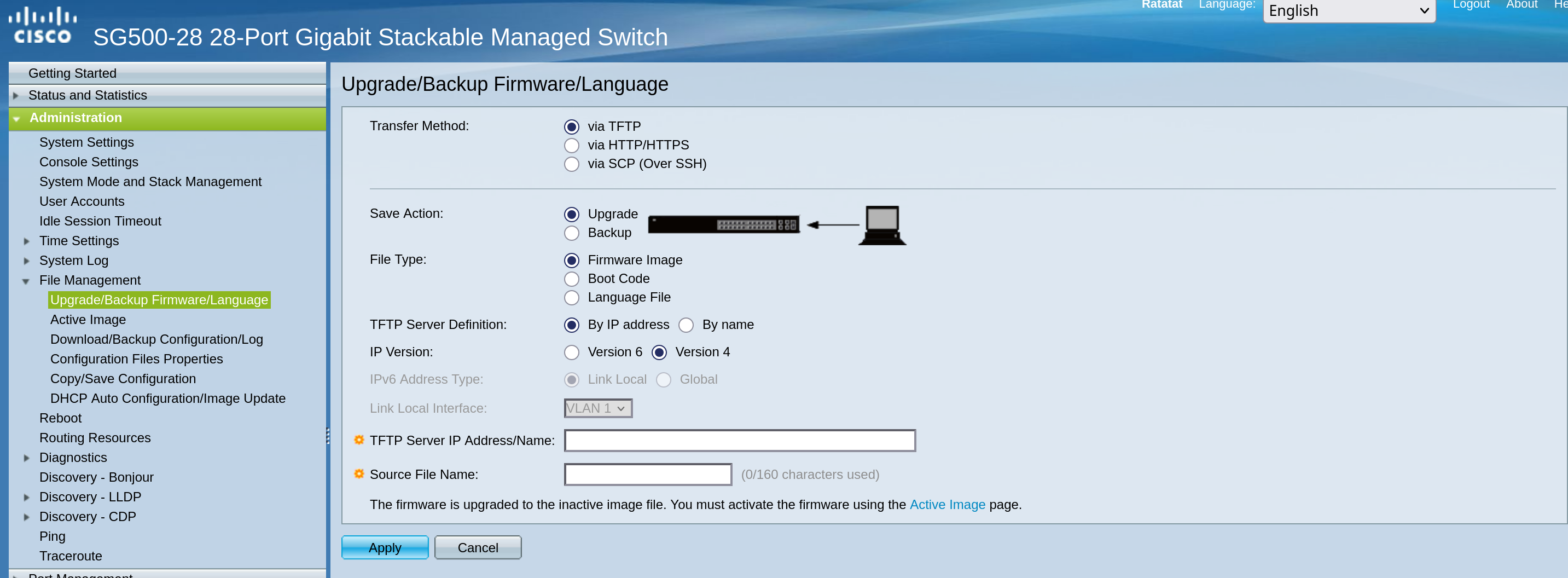
We already went over my simple FTP server setup with uftpd here.
I’m doing the exact same setup and then the UI here is straight forward.
Then we need to make sure to set the latest image as the “Active Image After Reboot” and we are good to go.
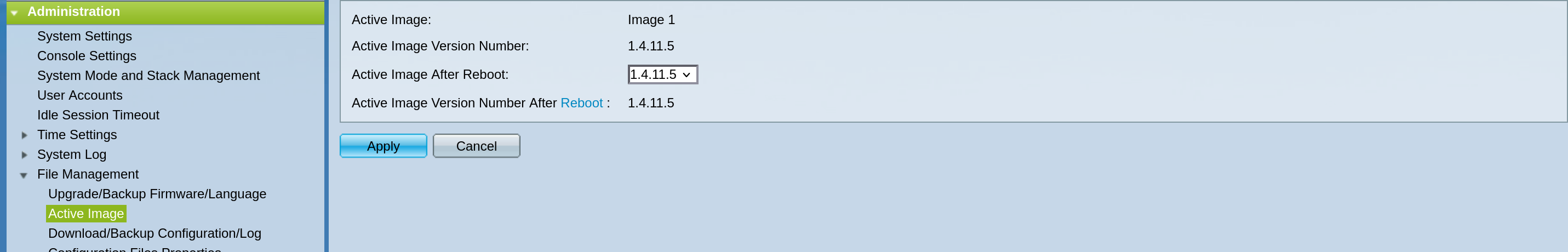
As I mentioned earlier I first had to go with the interim version, so rinse and repeat (or reboot in this case) a couple of times and we are on the latest possible version!
Basic Settings
First thing you want to do is set the system mode (L2 or L3) and the stack mode.
I go for standalone mode since I won’t be stacking and L2 mode since I will be trusting pfSense to do all the routing.
We set these first because they do require a system-configuration wipe to be applied.

Next things I set up:
- Hostname: SG500
- Delete the default IPv6 management interface, keep the IPv4 one
- Configure initial settings for time
I like to disable all discovery protocols: Bonjour, LLDP, CDP.
I also disable auto-smartport features.
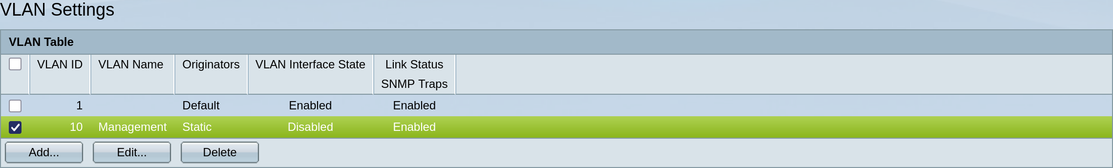
VLAN Setup
Now, let’s set up our VLANs.
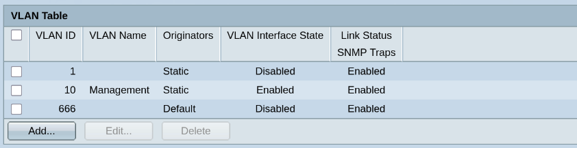
I like to set up a “dead” default VLAN that will also be set as the native VLAN where applicable.
Here we go with fan-favorite 666.
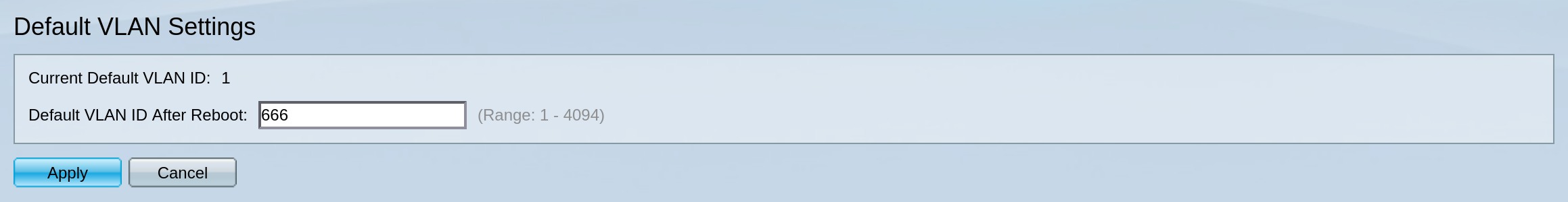
Let’s save and reboot for the default VLAN setting to be applied.
I will add VLAN 10 for management and configure VLAN 10 as the native VLAN in port 2.
This ensures we can still access the switch during the transition to VLAN 10.
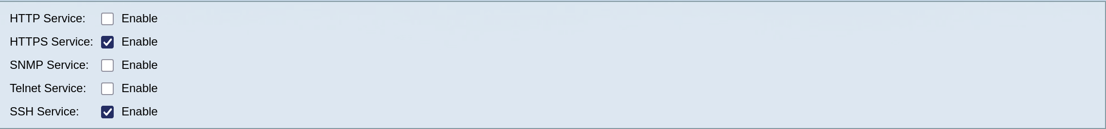
SSH Access
Now to change the management VLAN I will have to SSH into the switch, so this is a good time to enable SSH access and also disable HTTP access.
The switch uses an IOS-like CLI environment. It’s pretty intuitive if you are used to IOS.
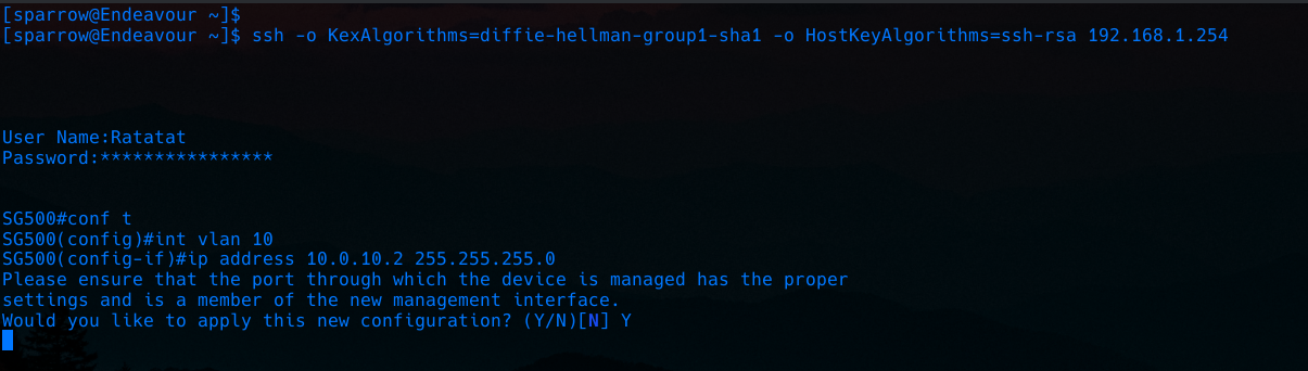
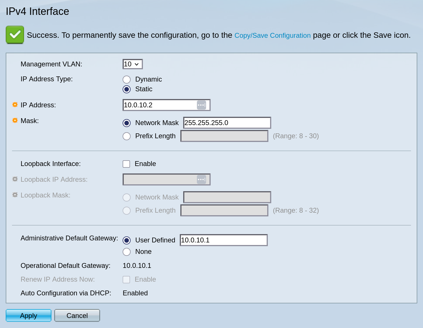
Because the switch is in layer 2 mode it can only have one management interface, since we just added an IP address to the VLAN10 interface (SVI) it will automatically become the new management interface.
And now I will switch to port 2 (GE2 on the switch) as the port used to connect to my PC’s NIC.
Let’s assign a new IP in the proper subnet and test connectivity.
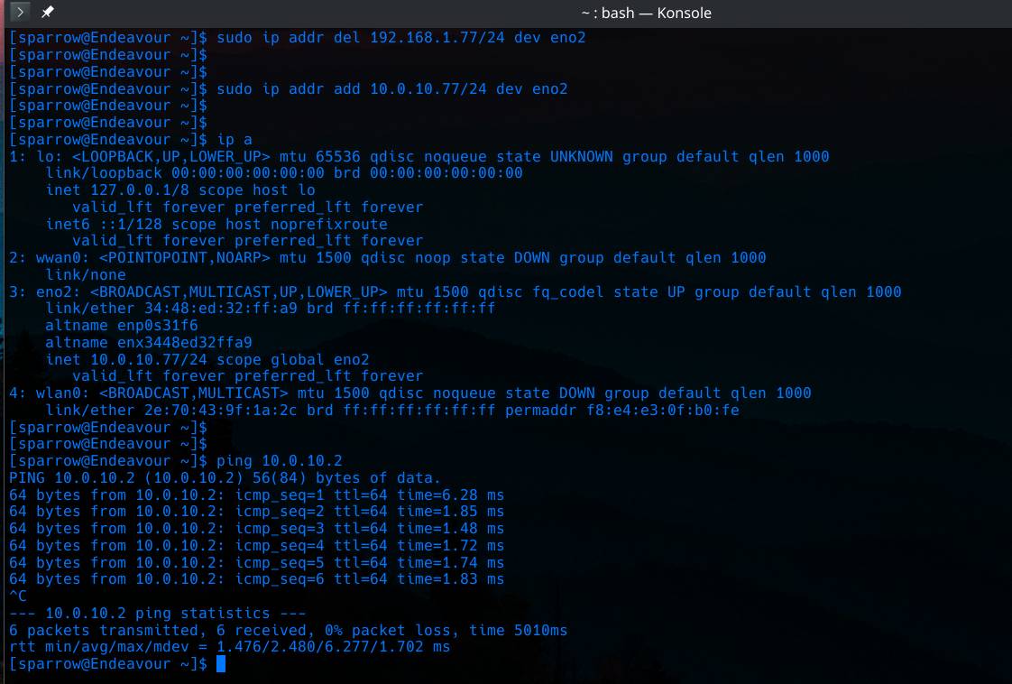
Beautiful!
Now back at the webUI make sure the only VLAN interface enabled on the switch is for VLAN 10.
Oops… I forgot to add a default gateway! Let’s add it now.
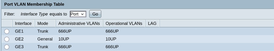
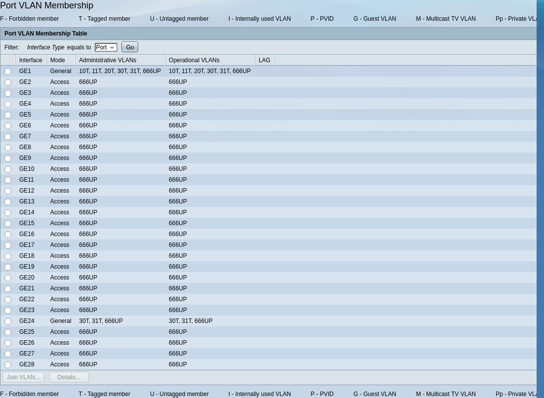
Adding the Rest of the VLANs
Now let’s define all the rest of our VLANs as we have them on pfSense and configure the ports.
| VLAN ID | Purpose |
|---|---|
| 10 | Management |
| 11 | AP Management |
| 20 | Guest |
| 30 | LAN |
| 31 | Lab |
| 666 | Dead - Default |
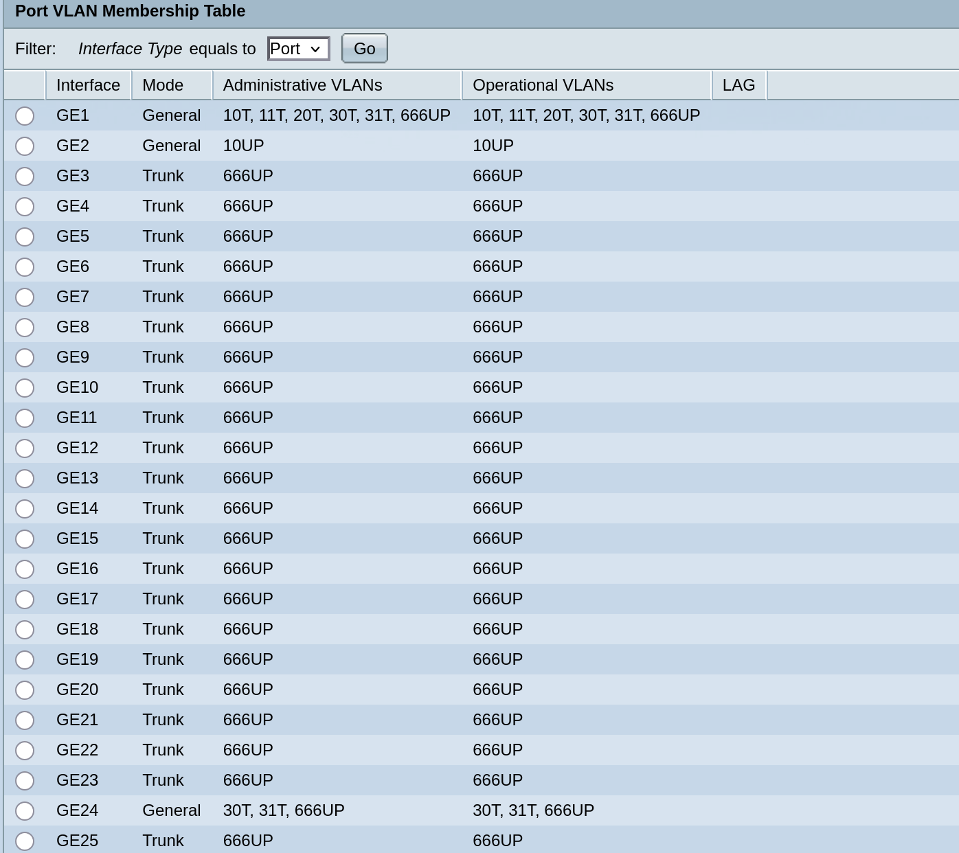
- Port 1 –> VLAN Mode: General, Admit Tagged Only –> connected to
pfSense’sigb2
→ Allow all of our VLANs to pass through it. - Port 24 –> similar setup, but only for VLANs 30 and 31, connected to PC’s NIC.
PC Setup
Let’s now connect our PC workstation to port 24 on the switch.
NetworkManager
Turning off the default NetworkManager connection.
nmcli conn down Wired\ connection\ 1
nmcli connection modify Wired\ connection\ 1 autoconnect no
Creating two new connections, one for the LAN network and one for the Lab network.
nmcli conn add type vlan vlan.id 30 con-name enp6s0.30 \
ipv4.method auto ipv6.method disabled \
dev enp6s0 autoconnect yes
nmcli conn add type vlan vlan.id 31 con-name enp6s0.31 \
ipv4.method auto ipv6.method disabled \
dev enp6s0 autoconnect no
This way by default the PC lives in the LAN network and gets an IP via DHCP.
If I want I can disable this connection and bring up the Lab connection and get an IP in that network.
Testing connectivity and finalizing configuration
We can now test if the switch management interface is reachable from this PC.
Path should be: PC(VLAN30 Tagged Traffic) –> Port 24(Trunk Mode VLAN 30 allowed) –> Port1(Trunk Mode VLAN 30 allowed) –> pfSense igb2.30 (routes to VLAN 10) –> Port1(Trunk Mode VLAN 10 allowed) –> 10.0.0.2 management interface.
All works well and we can now configure port 2 and the rest of the ports as access mode, with VLAN 666.
Also on pfSense, it’s now time to delete LAN on igb1 and rename OPT4 to LAN.
(relative to how we set up pfSense in part 3)
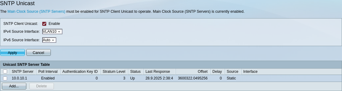
We can also now set up NTP properly for our switch.
Securing SSH Access
Next, let’s secure our SSH connection to the switch using public key authentication.
First we generate a compatible key on our PC.
ssh-keygen -t rsa
cat id_rsa.pub
And paste the public key on the switch UI.
Now we can have secure ssh access easily.
Well, the switch uses some older algorithms and needs specific SSH options to connect, so not too secure… and not too easily either :)
ssh -o KexAlgorithms=diffie-hellman-group-exchange-sha1 \
    -o PubkeyAcceptedAlgorithms=ssh-rsa \
    -o HostKeyAlgorithms=ssh-rsa Ratatat@10.0.10.2
Okay, in all seriousness these are weak/deprecated specifications for an SSH connection, but since it’s in the homelab (isolated management VLAN) and not exposed to the internet, we can live with the risk for now.
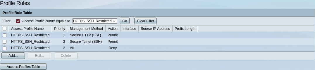
There are some specific ACLs provided for management access. Let’s configure some rules for good measure.
Creation of new profile:
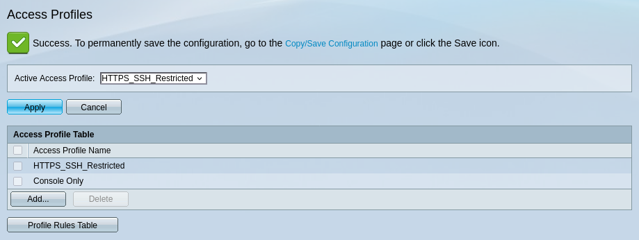
Allowing access only to HTTPS and SSH, all IPs allowed, we tighten further in pfSense.
STP and Security Features
Regarding Spanning Tree Protocol(STP), we can see that the switch has correctly identified the edge ports automatically.

In our case Root Guard and BPDU Guard do not make much sense, so we won’t enable these features.
The same applies for Port Security.
I will enable storm control (10%) on the port destined for my workstation.
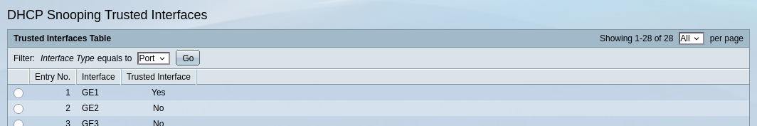
Finally, I will enable DHCP Snooping and set my interface connected to pfSense as a Trusted interface, leaving the rest untrusted.
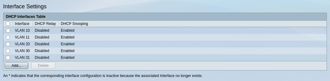
We will check how the DHCP binding table builds up over time and then implement Dynamic ARP Inspection as well.
Wrapping Up
And that’s all for our switch’s basic setup!
We will keep the management IP static in order to be easily able to SSH into the switch even if something is wrong with our DHCP server.
Don’t forget to save the configuration and keep a backup!
Next part:Building an IT Home-Lab Network | Part 5: Adding an Access Point